This article was written by Allan Short. Allan Short works in our Customer Call Centre at Carbatec Brisbane and is an esteemed woodworker.
History of the Longworth Chuck
The Longworth chuck features a self-centring mechanism that easily and quickly adjusts to the size of your turning by using a pair of disks which rotate against each other, drawing in and out the attached rubber jaws on a series of opposing arcs.
It is my understanding that Leslie Douglas Longworth of the Hunter Valley Woodturners developed the chuck in the late 1980′s. He showed it to the club and left it for them to examine however that night he passed away and the club refined Leslie's design and patented it in his name.
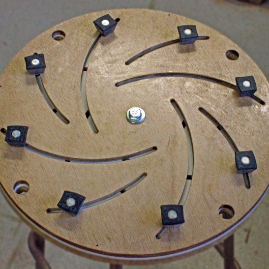
Steps to Making a Longworth Chuck
There are many versions of making a Longworth Chuck available on the Internet but here is my adaptation of this useful woodturning tool.
Material List
These are the materials I used. You can adjust these to anything you have lying around.
| 16mm MDF or Melamine |
4 x 25mm panel pins |
Large compass |
| 9mm ply for 2nd disc |
3/8” bolt and lock nut |
Router |
| 6mm ply for router template |
1/4" x 2" bolts for knobs |
1/4 straight router bit |
| Faceplate |
Rubber stops x 8 |
Knobs with 1/4" shafts x 8 |
| Screws to secure the Faceplate |
Teknatool 50mm Faceplate Ring (TK-6000) |
Polyethylene finish |
| Teknatool Cole Jaw Buffer Kit (TK-6030) |
Screws to secure the Faceplate Ring |
|
Step 1
Firstly, using a circle cutter or bandsaw, cut discs from the plywood (or Melamine) and MDF to a size appropriate to the swing of your lathe.
Step 2
The next step is to pin the two discs together using panel pins - within 20mm (3/4in) of the edges to avoid getting in the way when cutting the slots later - find the centre and mount the Faceplate Ring or Faceplate that will be used to attach the chuck to the lathe.
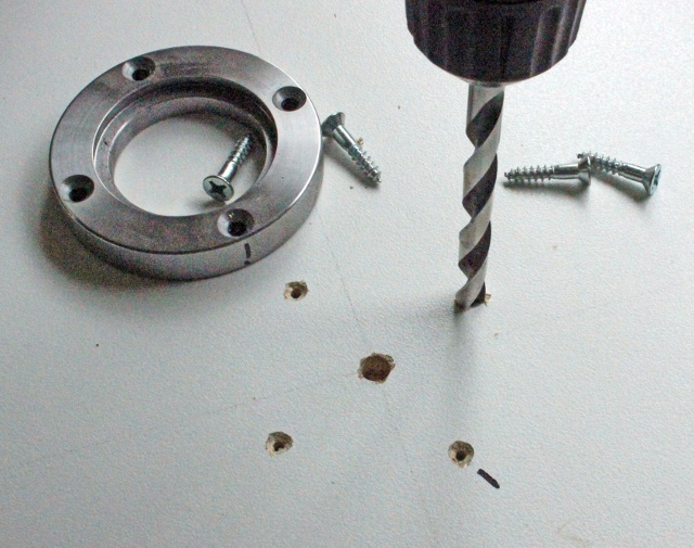
Note: I used a Faceplate Ring that will stay with the chuck. Using a Faceplate Ring allows for the chuck to be used on any lathe independent of the lathe type and spindle size as a centring chuck is used to grip the Faceplate Ring.
Countersink the holes securing the Faceplate Ring on both side to remove any burs.
Step 3
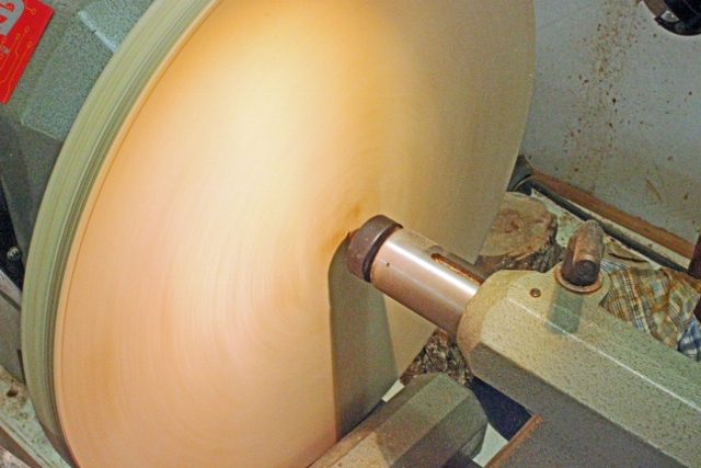
Mount the assembly on the lathe and true up the edge of the discs.
Step 4
With a live centre mounted in the tailstock mark the centre of the discs.
Step 5
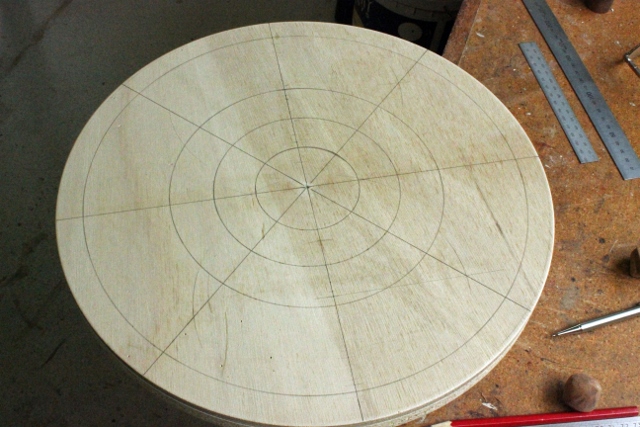
With a pencil and ruler mark a line across the diameter of the discs.
Step 6
Mark diameters at 45 and 90 degrees to the first line using a protractor or use a method like the ones on these links.
http://www.mathopenref.com/constangle90.html
http://www.mathopenref.com/constangle45.html
Step 7
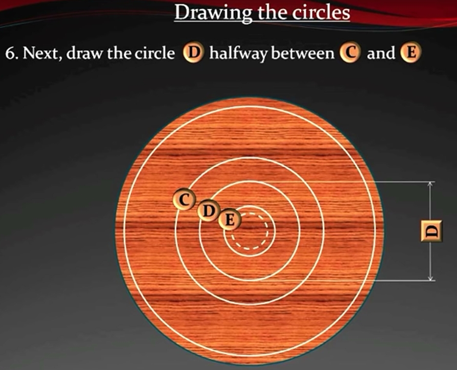
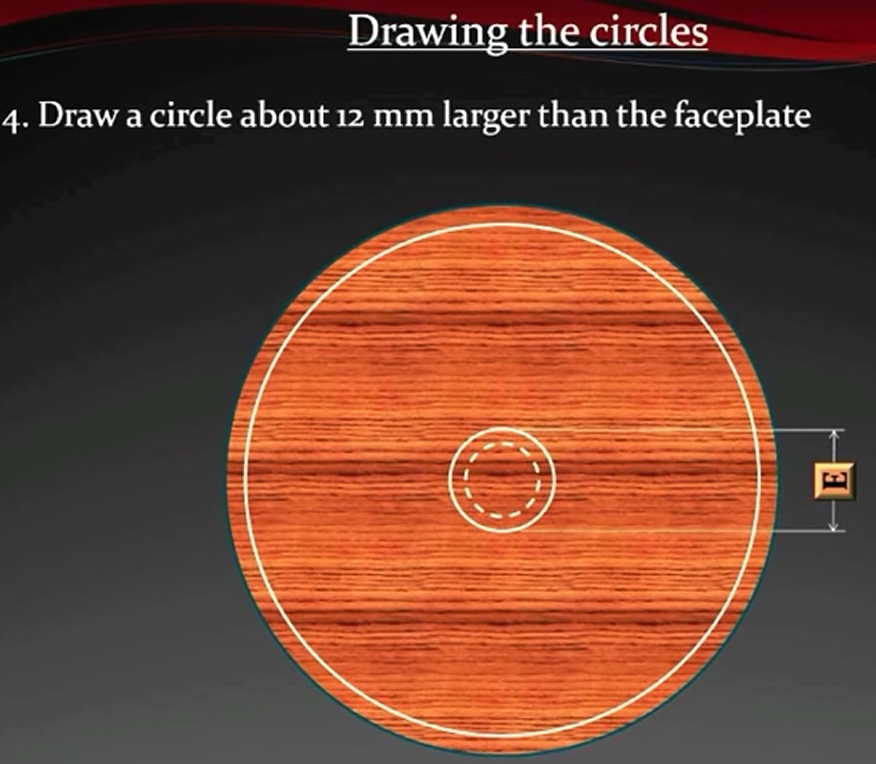
Draw four circles, the first slightly greater than the size of the faceplate, the second 20mm (3/4in) from the edge of the disc, the third halfway between the first and second, and the fourth halfway between the first and third.
Step 8
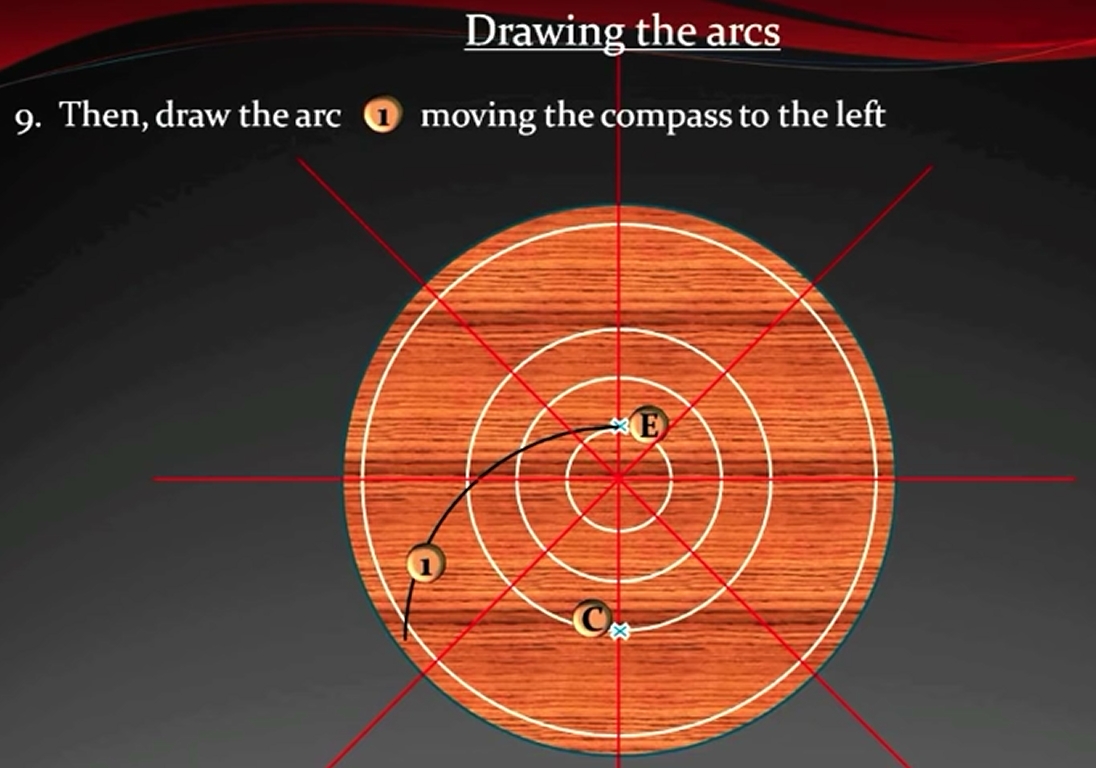
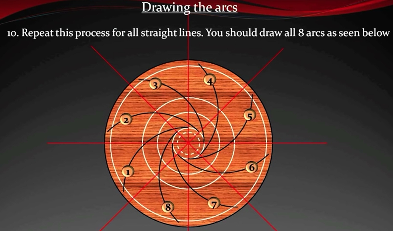
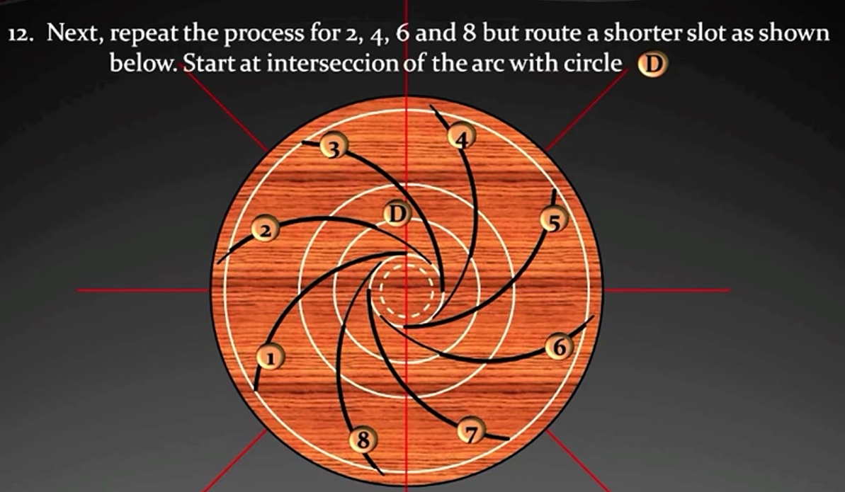
With the point of the compass centred at the points where the middle circle and the diameters intersect, draw arcs to the left tangent to the inner circle to a point where they reach the outer circle. Repeat for all 8 points of the lines and circle intersections.
NOTE: Every second arc should stop at the second circle (C in the diagram). This allows for strength in the chuck and also the stoppers in these slots can be removed to accommodate smaller bowls.
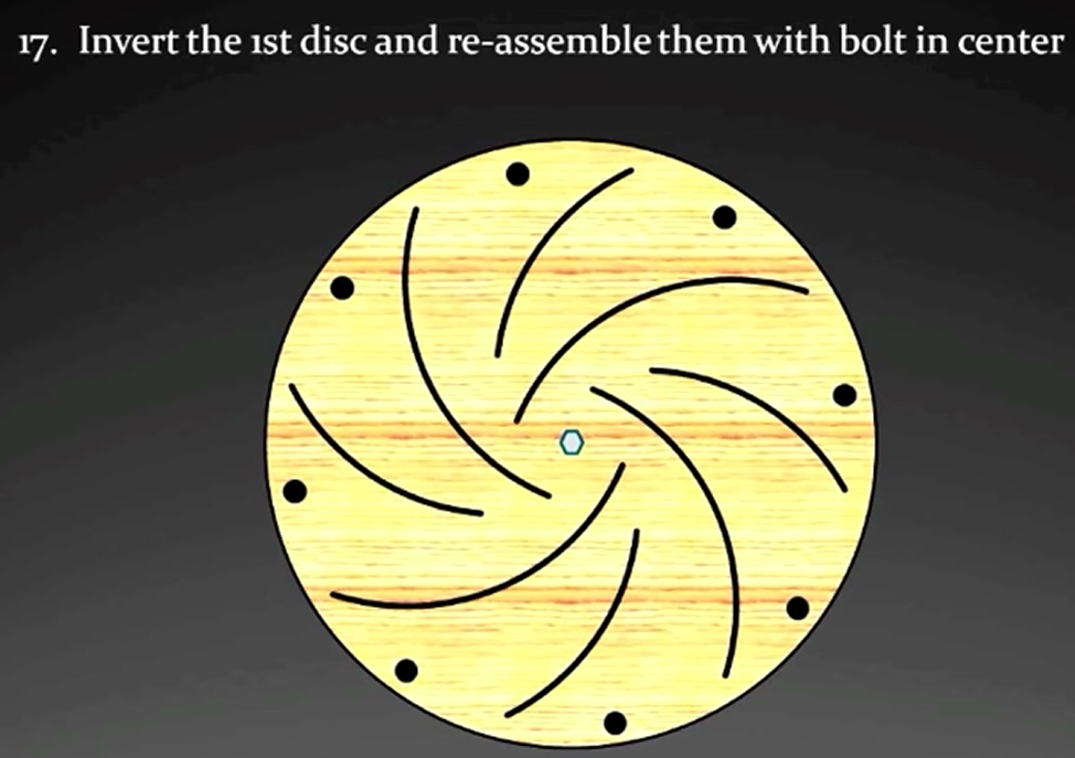
Note that while the spirals are all being drawn on the face disk the spiral slots will be cut through both disks at the same time so that the spirals are identical. After the disks are thus prepared, the base disk will be flipped over so that the slots will spiral out the opposite direction thus leaving a nominally square opening through which the gripper bolts will pass.
Step 9
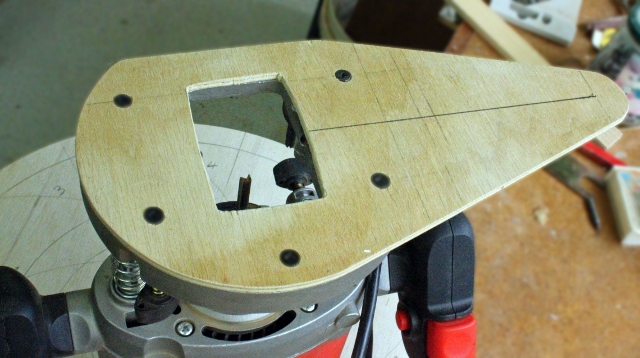
If you have a router with a trammel base plate, use it else make a template for the router like the one in the photo. The distance from point A to B is the distance of the arc you drew in step 8. Drive a nail through point B to act as a pivot.
Step 10
With the pivot point of the router centred on the same points as used to mark out, cut a slot the full length of the drawn arc. Take shallow cuts to avoid putting excessive stress on the 6mm (1/4in) bit.
Step 11
The next slot should stop halfway between the middle and centre circles.
Marking a fourth circle in step 8 will make this point easier to judge.
Step 12
Continue in this way until all the slots have been cut.
Step 13
Remount the assembly on the lathe and drill a 10mm (3/8in) hole right through for the axle bolt.
Step 14
With a drill press and Forstner bit drill finger holes through both discs 20mm (3/4in) from the edge at eight points around the perimeter.
Step 15
Separate the two discs and remove the panel pins. Reverse the front disc and place it against the back disc so that the routed arcs cross each other. Fit the axle bolt and adjust so the discs move easily.
Step 16
Sand the inside of the grooves so the chuck will slide smoothly.
Step 17
Fit the rubber buttons using the 6 x 50mm (1/4 x 2in) cap head bolts, thumb screws and washers. The Teknatool Cole Jaw Buffer Kit (TK-6030) is good for this task. Placing a washer between each rubber and the face of the chuck will enable them to slide more easily.
Step 18
Coat all exposed surfaces with Polyethylene finish to prevent moisture warping the chuck. Your Longworth chuck is now complete.